SE Series NDB Frequently Asked Questions
Southern Avionics has successfully implemented NDB systems for clients around the globe for safe...

How to change the frequency? See Section 6, Synthesizer Adjustment and Filters of the Technical manual.
How to change the Ident code? See Section 2, Coder Shift Register board of the Technical Manual.
Why does the transmitter keep shutting down under a Monitor-control state?
“V” led indicates a VSWR (Voltage Standing Wave Ratio) condition. This occurs when the forward power cannot radiate out of the antenna and is reflected back to the transmitter. Common reasons for this include coupler not being tuned, defective antenna, and filter board not being programmed correctly. The reflected power value is factory set at 20% which equates to a 2.62:1 VSWR. This value can be changed, but it is not recommended to exceed 30% reflected power, as high VSWR will damage the equipment.
“N” led indicates a loss of modulation. Common reasons for this include Mode Switch being in “CARR” position, Kwosyn board is defective, or Tone Keyboard is defective. Try cleaning the board contacts with a #2 pencil eraser.
“C” led indicates the carrier signal and modulation tone is present but there is no Ident code. Common reasons for this include Mode Switch being in the “CONT” position, the Coder Shift Register board being defective, and the Keyer Code board being defective. Try cleaning the board contacts with a #2 pencil eraser.
“P” led indicates a low power output. This is caused when the output power falls below a set value. This is factory set at 50% forward power. Common reasons for this include operating the transmitter at less than 50% forward power. This value can be changed with no damage to the equipment.
A common reason for any of the above conditions is a misaligned Monitor control board.
Refer to Section 5.1.9 or the correct section, Monitor Control PWB, in the Technical Manual for the setup procedure.
When operating on DC voltage, the output power is low.
The DC board is designed for operation of only 80% forward power. This alerts the technician to a problem with the AC input voltage.
If 80% forward power is unattainable, the DC voltage level is probably set to low. Refer to Section 5.1.10, DC Board, of the Technical Manual to adjust the voltage.
The Keyer rate (Ident) speed is incorrect.
This value is factory set to 8 Hz for an 8-baud (125 ms bit) keying rate. This can be adjusted anywhere from 6 to 18 Hz. To change the keying rate refer to Section 6, Keyer, in the technical manual.
Why does the transmitter keep blowing fuses?
If the AC power supply board (SLP29910) is blowing fuses, the input power is hooked up incorrectly.
If the SPA or DMOD board is blowing fuses, do NOT replace the fuse and try again!!! There could be a problem causing the fuse to blow. Turn off input power and discharge the large blue capacitor to the left of the AC power supply board. Remove both the SPA and DMOD board from the transmitter. Using a multimeter, measure the resistance of the final FETs on both boards.
The SPA board should measure:
Drain to Source is approximately 2.7 Meg Ohms.
Drain to Gate is approximately 2.7 Meg Ohms.
Source to Gate is approximately 5 Ohms.
The DMOD board should measure:
Drain to Source is approximately 130k Ohms.
Drain to Gate is approximately 130k Ohms.
Source to Gate is approximately 1.2k Ohms.
If any of these measurements are significantly lower, the transistors will need to be replaced. It is best to replace both transistors at once versus one at a time.
For further troubleshooting; refer to Section 2, Modulator and Power Amplifier sections in the Technical Manual.
Why do I have no RF output?
This could be caused by a number of variables including defective SPA and/or DMOD, filter board is programmed wrong, the coupler is not tuned, or the antenna is defective.
To isolate the problem, it is necessary to remove the coupler and antenna from the system. Refer to Section 2 of the technical manual and find the Transmitter Diagram (DWG 4792or SLE100SA). Turn off input power and turn the RF switch to OFF. Move the blue wire from TB3-3 to TB3-2. This places the RF output onto the two gold resistors mounted to the front panel. These two resistors are the internal 50 Ohm load and will act as an antenna for troubleshooting purposes.
NOTE: The internal 50 Ohm load is not designed for continuous operation. Limit full power operation to fifteen (15) minutes.
Reapply input power and turn the RF switch back on. Place the MONITOR switch in the DSBL position to prevent the transmitter from shutting down. SLOWLY increase the RF level pot. While increasing the RF level, pay close attention to the PA volts, PA current, and reflected power. Do NOT allow reflected power to exceed 30% or the PA Voltage to exceed 90 Volts.
The PA Voltage and PA Current should be as follows:
For a 25-Watt transmitter: 25 to 45 volts and 0.8 to 1.3 Amps.
For a 50-Watt transmitter: 35 to 55 volts and 1.1 to 1.6 Amps.
For a 100-Watt transmitter: 50 to 80 volts and 1.5 to 2.3 Amps.
If there is PA Voltage and no PA Current, the filter board is not programmed correctly or there is a problem with the SPA or DMOD board. Refer back to step #2 for the filter board. A properly programmed filter board will measure less than 10 Ohms from pin 5 to pin 20. Refer back to step #7 for the SPA and DMOD.
If there is PA Current and no PA Voltage, the problem is likely in the DMOD board (possibly the SPA). Refer back to step #7 for troubleshooting the SPA and DMOD.
Why does the remote panel not work?
If all of the LEDs are constantly illuminated, the control cable connecting the transmitter and remote panel is hooked up incorrectly.
Refer to Section 4, Transmitter Installation, of the technical manual. Find the INTERCONNECTING WIRE DIAGRAM and the INPUT / OUTPUT TERMINAL BLOCKS diagram.
Next, refer to the “Local Radiobeacon Control Unit” in Section 4. This will isolate the problem to the transmitter or the Remote panel.
Refer to the “Remote Radiobeacon Control Panel” in Section 4.
If using the Serial board only (SLP24300):
Ensure the connections on TB3-1, TB3-2, and TB3-3 on the transmitter are connected per the interconnecting wire diagram. TX and RX are reversed on the Remote panel.
If using the Modem board only (SLP33600):
Ensure the jumper J1 is installed ONLY on the Modem board for the Remote Panel. The remote operation will not work if J1 is installed on both modem boards.
What type of cable do I use to connect the transmitter to the coupler?
For distances less than 300 feet, RG58 is recommended. For distances over 300 feet, RG8 is recommended. It is recommended not to exceed 1,000 feet.

Southern Avionics has successfully implemented NDB systems for clients around the globe for safe...
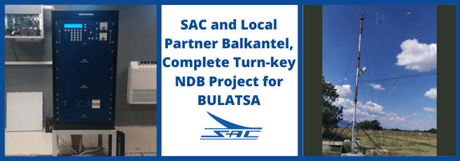
With local partner Balkantel, SAC completes a turn-key NDB Project for the Bulgarian Civil Aviation...
Leave a Comment